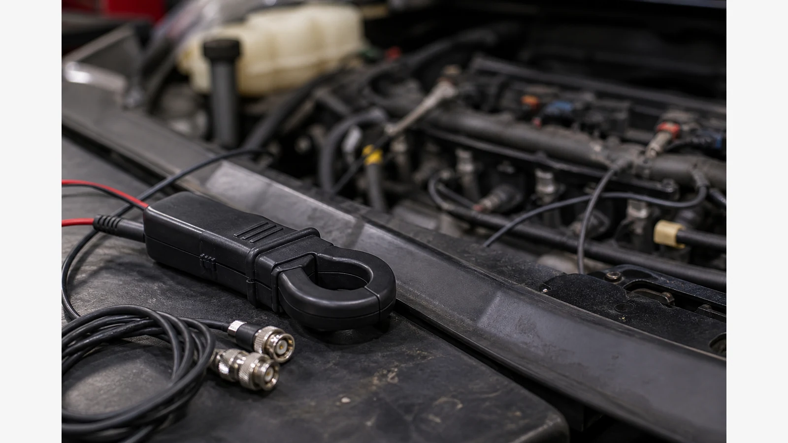
Fuel injector waveform oscilloscope UK: voltage and current clues
A fuel injector waveform on an oscilloscope shows circuit integrity and pintle behaviour that scan PIDs often miss. Voltage traces confirm whether the injector is being driven; adding a current clamp helps compare mechanical response across cylinders after codes and noid-light checks stall.
UK independents regularly see rough running with inconclusive codes, where a noid light only proves that a pulse reached the connector. Case writing from AutoIQ UK shows multi-channel injector voltage and current captures diagnosing harness resistance and delayed pintle behaviour. Snap-on UK technical focus documents two- and three-channel fuel injector voltage and current tests for mechanical assessment on low-pressure injectors.
Problem: codes and noid lights stop short
Freeze-frame data may show fuel trims or misfire counts without proving a sticky injector, high-resistance splice, or weak driver. A noid light answers “is there a pulse?”, not “does the pintle move like its neighbours?”.
Decision path for UK workshops
- Voltage-only first. Capture injector control voltage on a known-good ground; confirm on/off edges and on-time consistency at idle.
- Add current when comparing cylinders. A low-amp clamp on the supply or control path (per clamp instructions) reveals ramp shape and relative opening behaviour.
- Interpret knee and flyback cautiously. Pattern differences matter more than memorised millisecond thresholds without OEM data.
- Stay within injector class. Low-pressure port injectors are the usual teaching path. Piezo and high-pressure direct-injection systems need OEM guidance and attenuator awareness — do not treat them as the same test.
Noid light vs scope capture
| Check | What a noid light proves | What a scope capture can add |
|---|---|---|
| Driver pulse present | Yes / no indication at the connector | Edge quality, pulse width consistency, missing pulses under load |
| Harness integrity | Often inconclusive | Voltage drop clues and cylinder-to-cylinder mismatch |
| Mechanical pintle behaviour | Not shown | Current ramp / relative delay clues on suitable low-pressure systems |
| Parts decision | Not sufficient alone | Still needs confirmation path — never buy on a single pretty waveform |
Who should not start here
Do not begin with piezo or high-pressure DI injector scoping unless you have OEM procedures and correct attenuation. Also skip inventing amp ratings or claiming any particular clamp is included with a scope kit unless your purchase paperwork confirms it.
Reader next action
Build a three-cylinder comparison checklist (idle voltage, loaded voltage, then current if available) before buying more channels. Pair injector work with related diagnostics such as ignition waveform testing, relative compression triage, and a staged accessories buying order. For broader USB scope context, see the car oscilloscope diagnostic tool buyer’s guide.